Phlogiston Spar Rivet Differences to plans
I’ve been laying out the ribs and cutting the support angles and I’m finding that the TR plans seem to be more accurate to the Phlogiston spars than the HR plans, including the notes on https://vincesrocket.com/ for HR plans corrections.
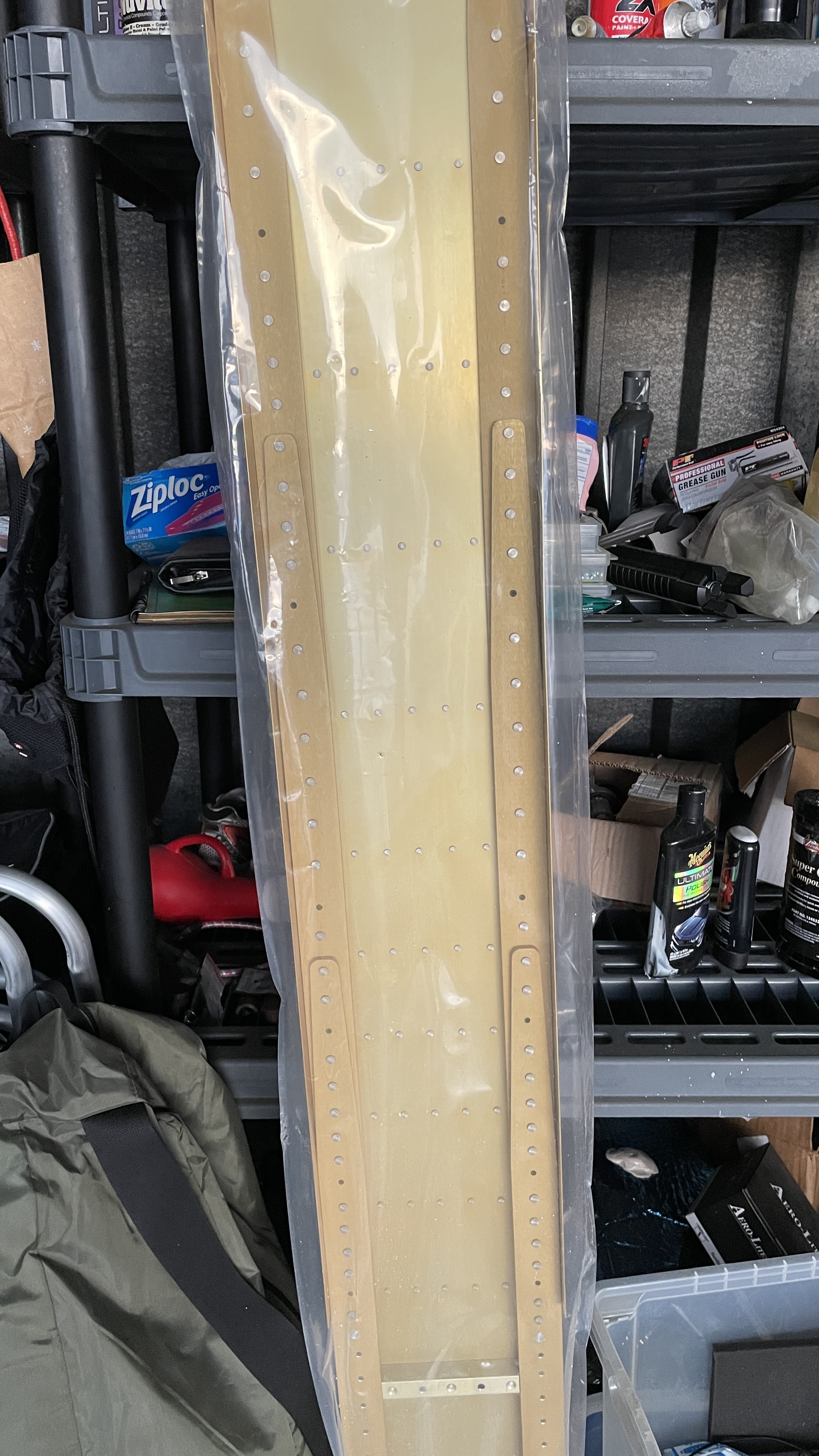
But I’m still finding some oddities in the spar. The places where TR plans say to leave a hole and where to put a rivet aren’t consistent.
For example, there are some rivets installed before station 18 1/4 that show should be open, and has a flush rivet installed.
The station before 18 1/4 is open, but 18 1/4 has a rivet
Or the two locations beyond 77 5/16 are open, and 77 5/16 has a rivet.
And a few more like that between these two stations.
(Click on the image to get a higher resolution image. You might have to click twice to get the BIG picture.)
The first image is the Phlogiston spar image in parallel with the Team Rocket plans. Red arrow = remove a rivet, green arrow = insert a rivet.
The second image is a single shot of the spar.
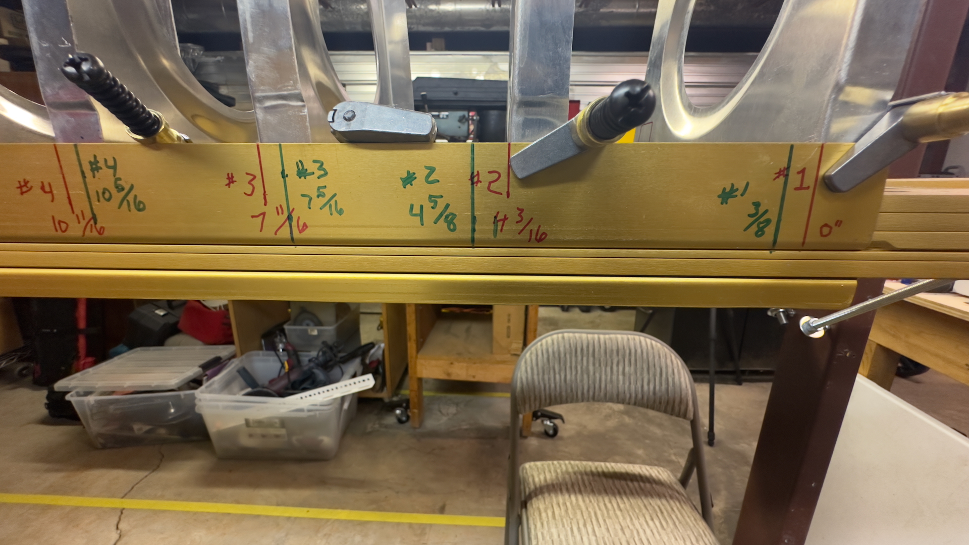
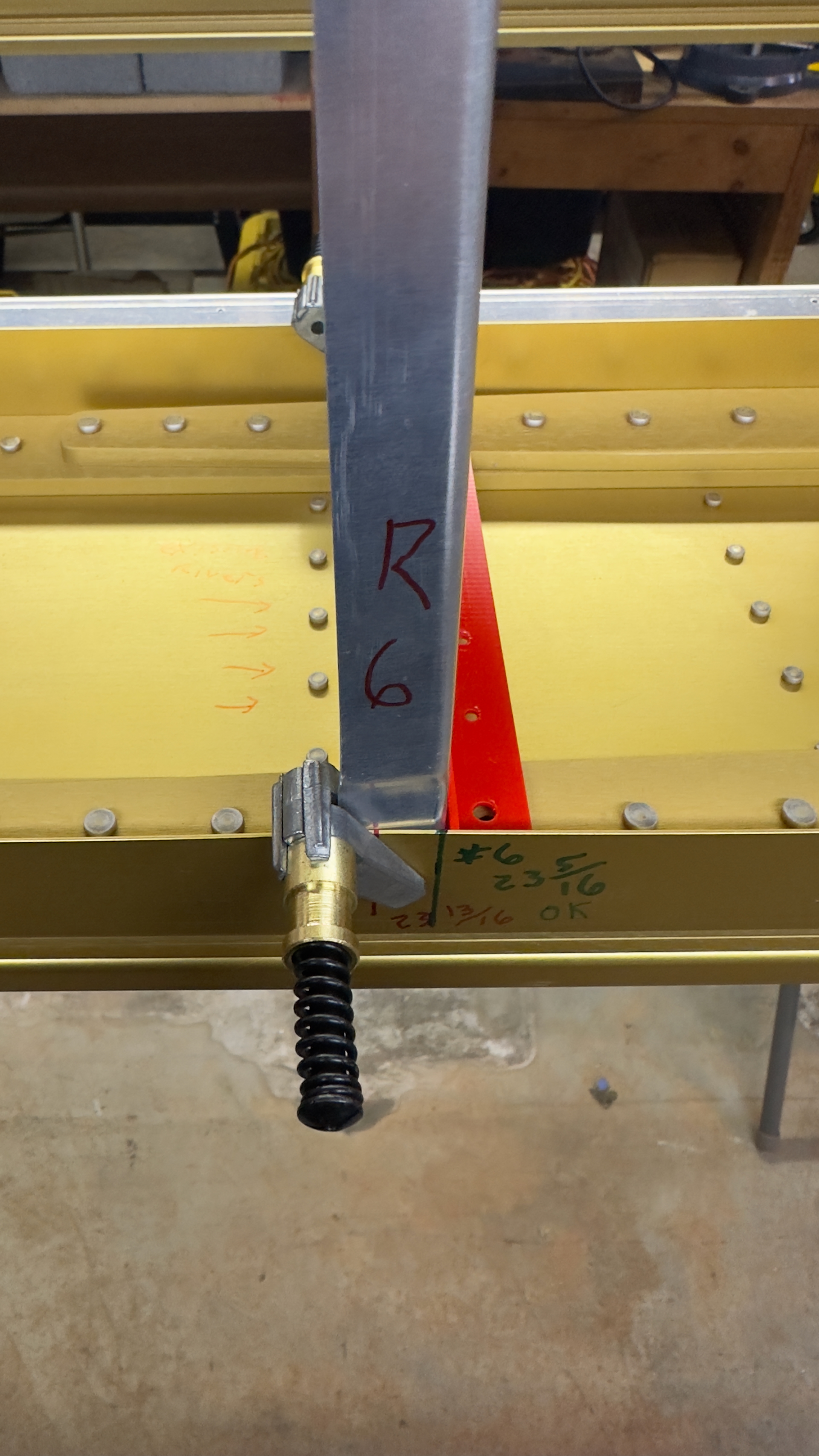
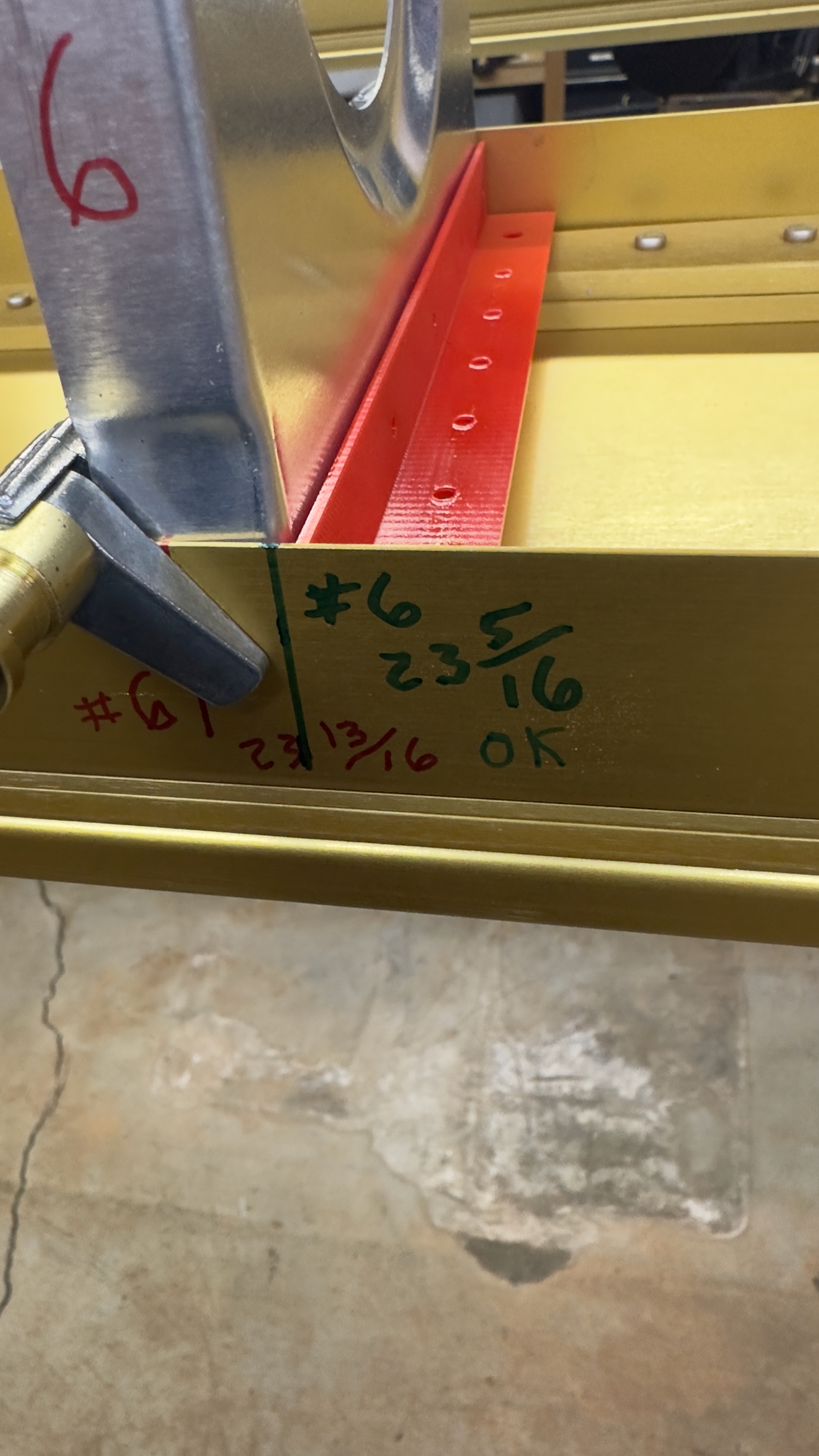
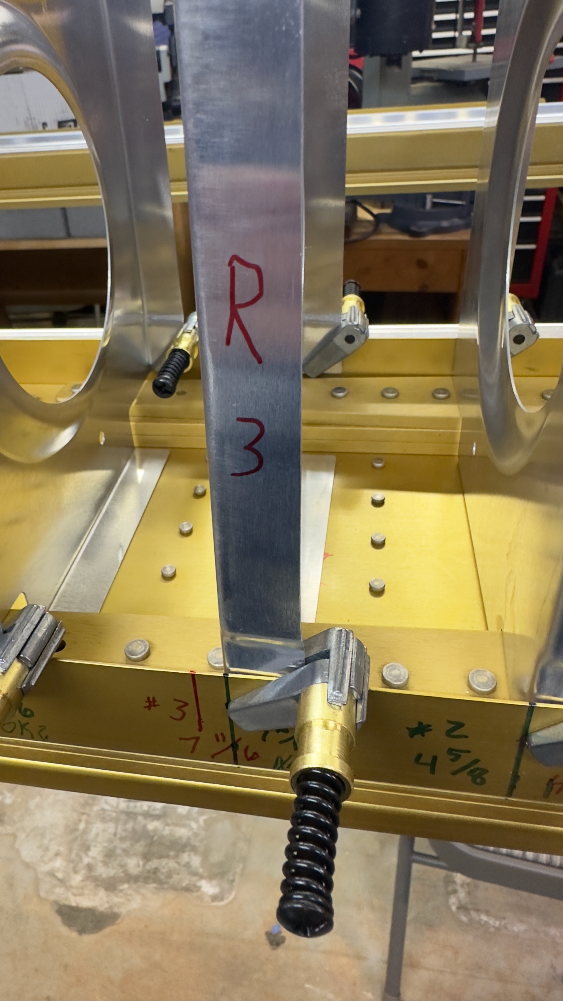
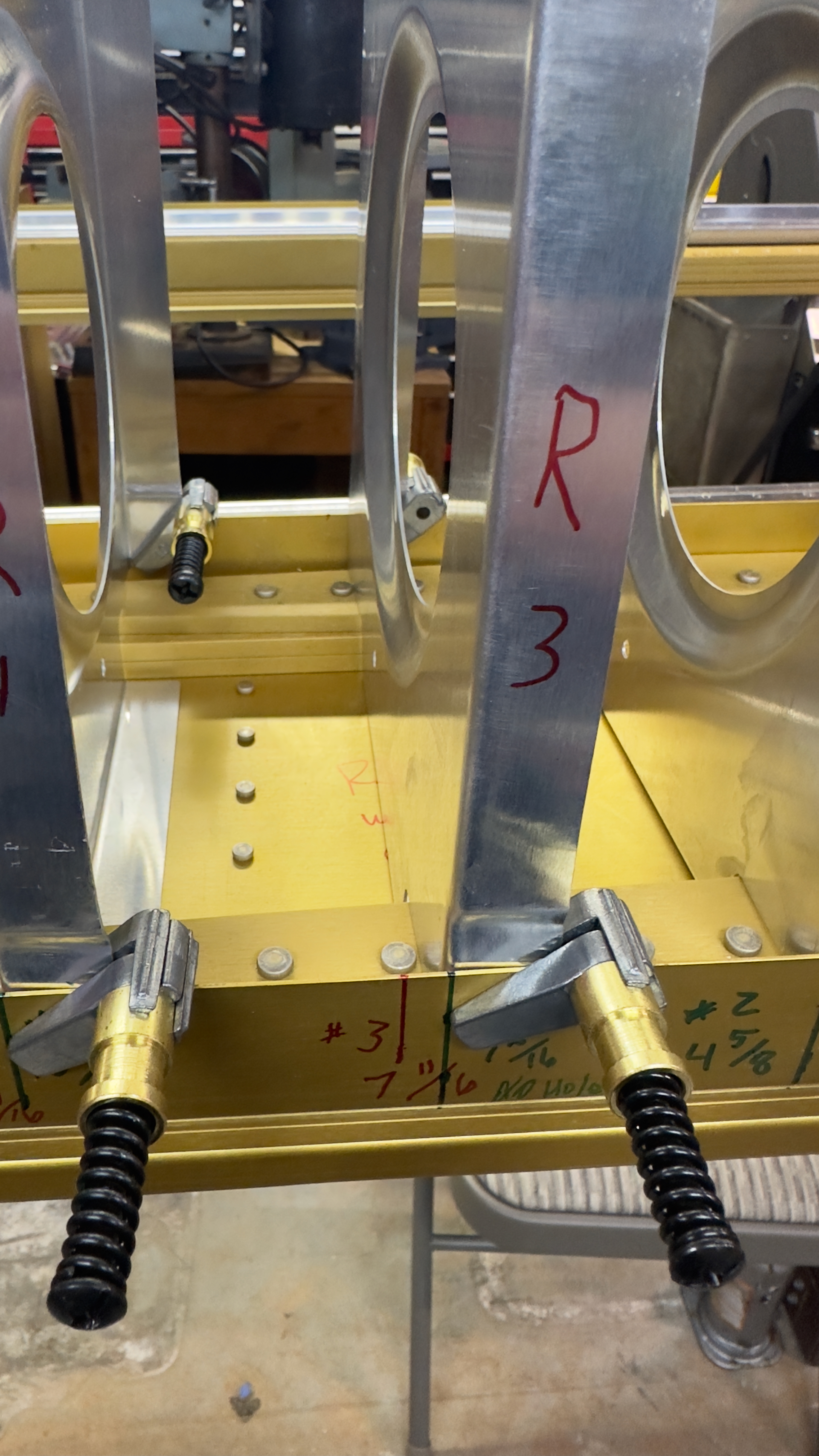
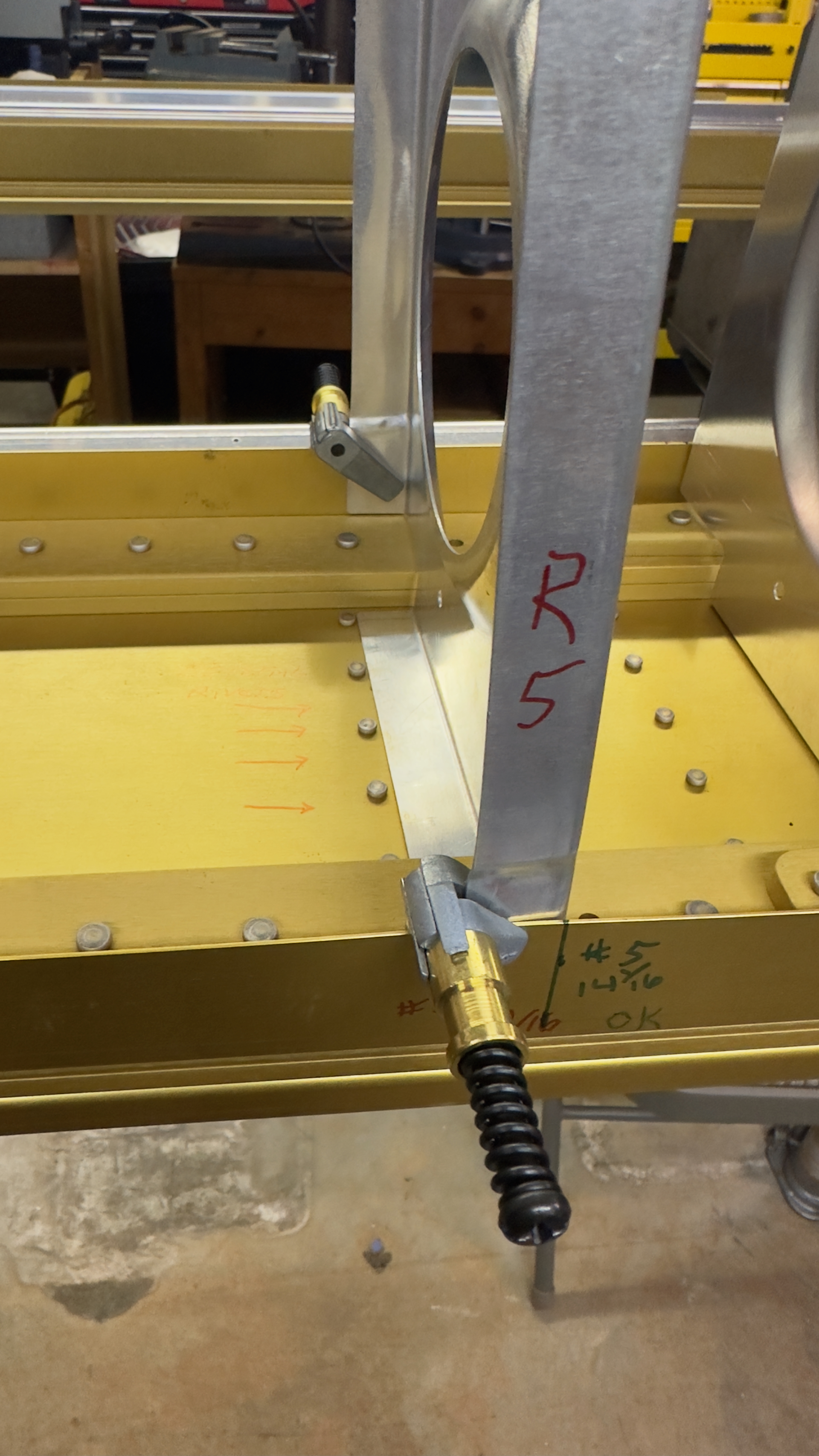
The rest of the images are of the other ribs placed in the green (team rocket plans) locations that are ok.
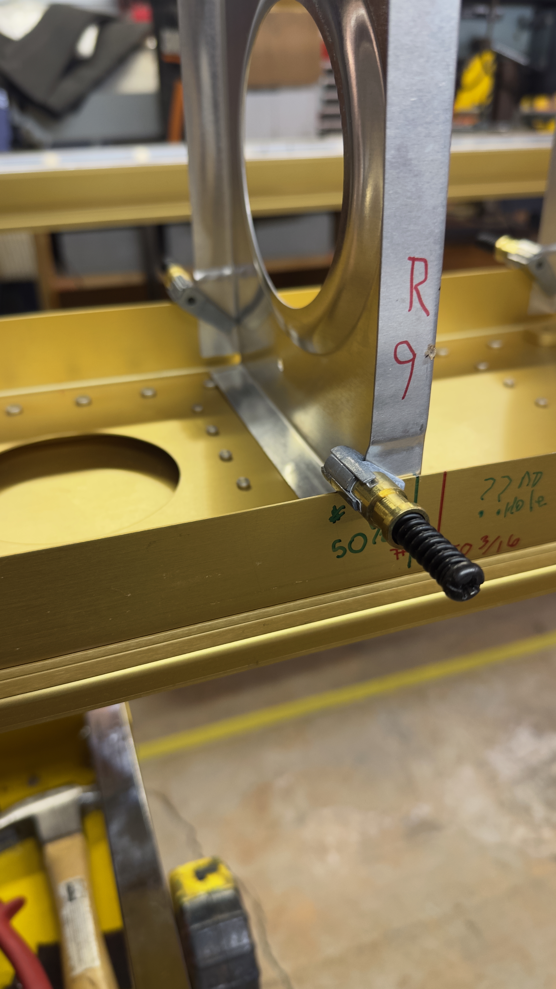
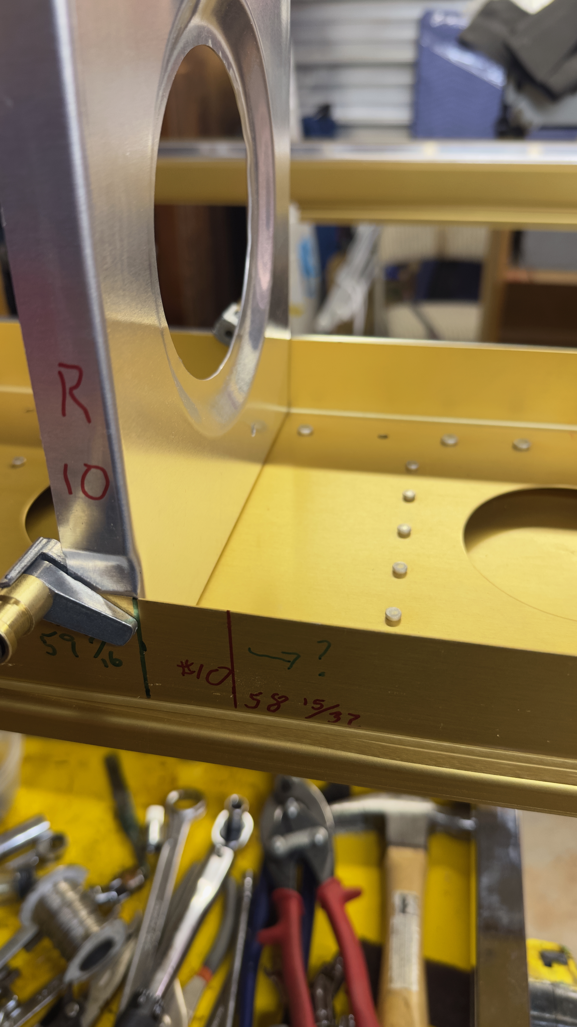
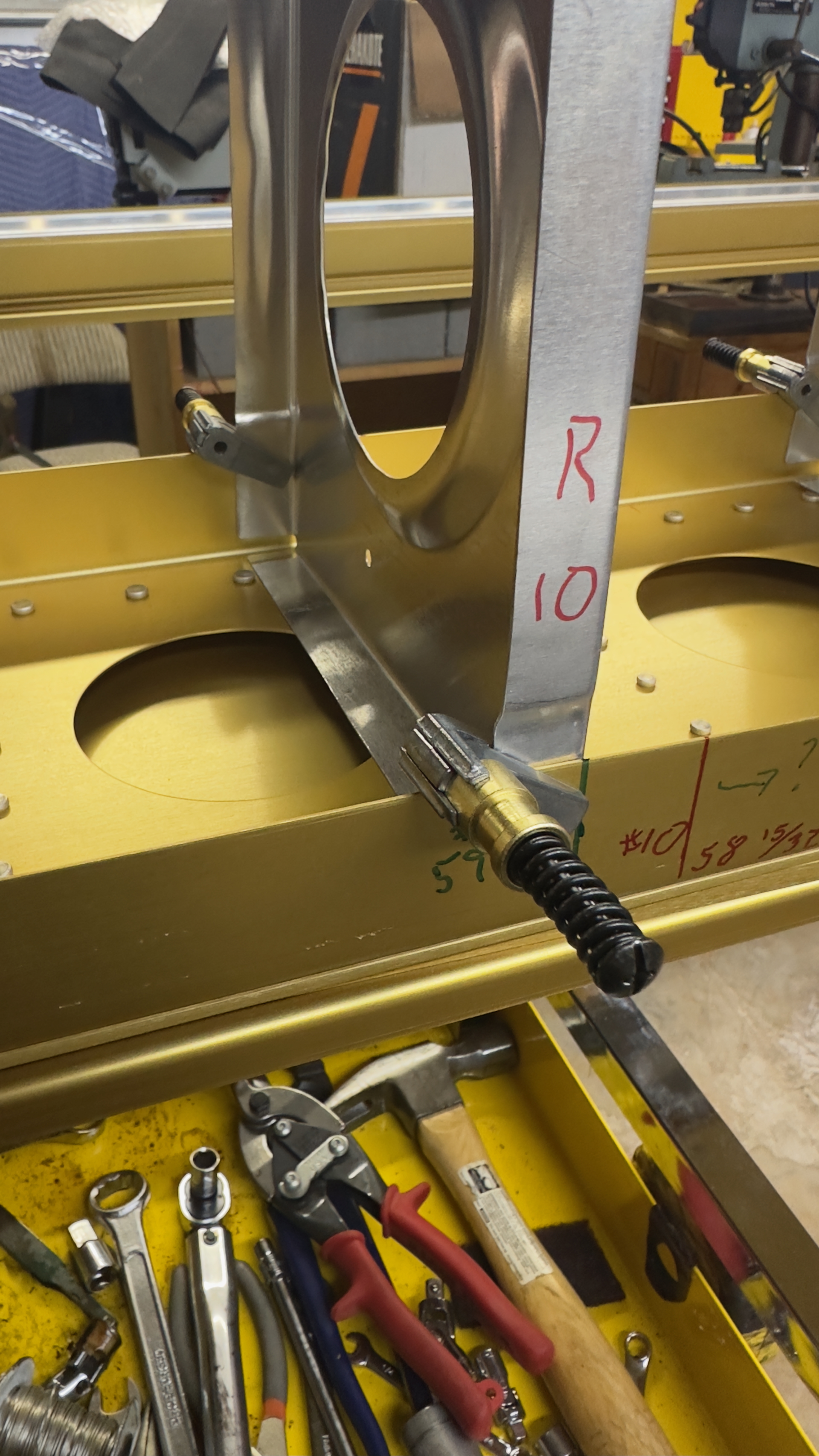
I still have a question about Rib #10 (See last image in the post.) I might need to drill out the rivet to the inside of Rib #10, and fill in the hole to one more over with a rivet.
I think I also need to drill out a rivet for rib #9 (See image below)
(Update: I’ve found that there were a small number of spars that had some rivets placed in holes that should be open, and some that are open that should have a rivet. I think there are 4 rivets total that need drilling out and 2 rivet holes that need to be filled with the monster 3/8 rivets. In particular, I need to remove a rivet for the #3 rib, add a rivet outboard of #8 rib, and remove a rivet for #9 rib.)

